Why Hidden Equipment Faults Are More Dangerous Than Visible Failures
The Real Cost of Undetected Equipment Issues
Equipment failures rarely announce themselves loudly. The most destructive faults develop silently, a transformer slowly overheating, a bearing wearing internally, electrical resistance building in a connection. By the time a failure becomes visible, you’ve already lost money and risk.
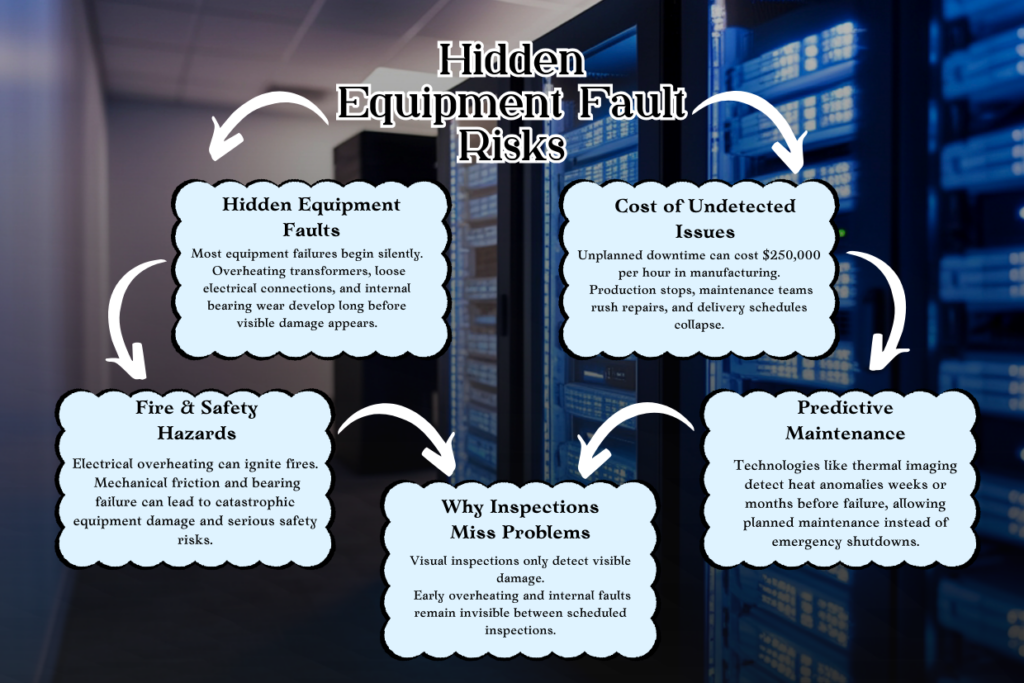
Unplanned downtime from hidden faults averages $250,000 per hour for manufacturing facilities. Production stops, teams scramble, customers see delays. A single unexpected equipment failure can cascade across dependent systems, creating compound losses.
Beyond production loss, hidden electrical faults create fire hazards. An overheating connection that goes undetected can eventually ignite, putting personnel at risk and threatening entire facilities. Mechanical friction-related heat buildup can lead to catastrophic bearing failure, potentially causing explosions in high-pressure equipment.
Compliance matters too. Industrial facilities, data centers, and energy operations face regulatory requirements for equipment safety. Undiscovered faults during audits can result in operational shutdowns, fines, or loss of certifications.
Why Traditional Inspections Often Miss Early Warning Signs
Visual inspections are reactive and intermittent. An engineer walking through a facility might spot visible damage, but early-stage electrical overheating or internal bearing wear leaves no surface clues. Most inspections happen monthly, quarterly, or annually, long gaps where conditions can deteriorate rapidly.
Periodic monitoring creates blind spots between inspection windows. A transformer might overheat for three weeks before the next scheduled inspection catches it. Human error compounds the problem: fatigue, insufficient training, or simple oversight means inspectors miss subtle abnormalities.
The Shift Toward Predictive Maintenance
Forward-thinking organizations have moved from reactive “fix it when it breaks” approaches to predictive, condition-based maintenance. Instead of replacing equipment on a schedule or waiting for failure, they monitor actual equipment condition and intervene precisely when needed.
Non-destructive testing technologies, especially thermal imaging, enable this shift. They let you detect deterioration weeks or months before failure, turning reactive crises into planned maintenance windows.
How a Thermal Imaging Camera Works (Without Technical Overload)
What Is a Thermal Imaging Camera?
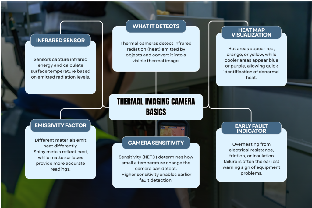
A thermal imaging camera detects infrared radiation (heat) emitted by objects and converts it into a visual image. Unlike visible-light cameras, thermal cameras “see” temperature differences. Hotter objects emit more infrared radiation; cooler objects emit less. The camera creates a heat map where warmer areas appear in bright colors (red, orange, yellow) and cooler areas in darker colors (blue, purple).
How Infrared Technology Detects Temperature Differences
Every object above absolute zero emits infrared radiation. A thermal camera has a sensor that captures this radiation and calculates the actual temperature of the object. This is where emissivity matters, a property that describes how effectively a surface emits infrared radiation. Shiny metals and reflective surfaces have lower emissivity; matte, darker surfaces have higher emissivity. Understanding emissivity prevents misreadings.
The camera’s sensitivity (measured as NETD, Noise Equivalent Temperature Difference) determines how precisely it can detect small temperature variations. A sensitive camera might detect a 0.05°C difference; a basic one might need 2–3°C to register a change. For early fault detection, sensitivity matters significantly.
Why Heat Is an Early Indicator of Equipment Failure
Electrical resistance: Loose connections or overloaded circuits create resistance that converts electrical energy into heat before the circuit fails electrically. A thermally imaged loose terminal connection may show 20°C hotter than surrounding connections, a red flag weeks before the connection fails.
Mechanical friction: Bearing wear increases friction. Rising friction means rising temperature. A bearing near failure often shows measurable heat increases before noise, vibration, or catastrophic failure signals anything wrong.
Insulation breakdown: Electrical insulation deteriorates from heat, moisture, and age. As insulation fails, electrical leakage increases, generating localized heat before a short circuit occurs. Thermal imaging often detects this stage of degradation.
Common Misconceptions About Thermal Imaging
“It sees through walls.” Thermal cameras detect infrared radiation from surfaces, not through barriers. A wall blocks infrared just as it blocks visible light. Thermal imaging is strictly a surface-temperature technology.
“It replaces all other inspection methods.” Thermal imaging is one tool in a diagnostic toolkit. It tells you where something is overheating, but not always why. You may still need multimeter testing, vibration analysis, or internal inspection to confirm root causes.
“It only works in complete darkness.” Thermal imaging works in daylight, darkness, and fog. However, reflective surfaces and direct sunlight can introduce false readings. Controlled environmental conditions improve accuracy.
What Hidden Equipment Faults Can a Thermal Imaging Camera Detect?
Electrical System Faults
Loose connections create thermal hotspots at contact points. Overloaded circuits show temperature rises as current density increases. Phase imbalance in three-phase systems causes uneven heating across phase conductors. Transformer cores overheat when windings degrade or load exceeds capacity.
Mechanical and Rotating Equipment Issues
Bearing wear increases friction, raising bearing temperature. Misaligned shafts create rubbing friction and localized heating. Friction-related heat buildup in gearboxes, pumps, and motor bearings provides advance warning before mechanical failure.
Building & Infrastructure Problems
Water intrusion behind walls reduces insulation effectiveness, creating cooler spots on thermal scans. HVAC duct leaks and insulation failures appear as thermal anomalies. Heat escaping through building envelopes indicates energy waste and degradation.
Industrial Applications Across Sectors
Manufacturing plants detect motor overheating, bearing wear, and electrical faults. Data centers identify cooling failures before server damage occurs. Energy facilities monitor transformer health and circuit integrity. Commercial buildings assess HVAC performance and building envelope integrity.
Thermal Imaging vs Traditional Inspection Methods
| Method | Thermal Imaging | Visual Inspection | Multimeter/Point Testing |
| Detection Range | Non-contact, full systems | Surface-only, visible damage | Single-point measurements |
| Speed | Minutes to scan large areas | Hours to inspect thoroughly | Time-consuming per point |
| Early Detection | Yes, catches thermal anomalies | No, waits for visible signs | Partial, only test locations |
| Documentation | Thermal images & data trends | Notes & photographs | Numerical readings only |
| Training Required | Moderate, emissivity, baselines | Minimal | Moderate, electrical safety |
| False Positives | Possible without proper context | Unlikely (visible is real) | Minimal if interpreted correctly |
| Cost | Camera & trained operator | Minimal training & tools | Multimeter & technician |
Thermal Imaging vs Visual Inspection
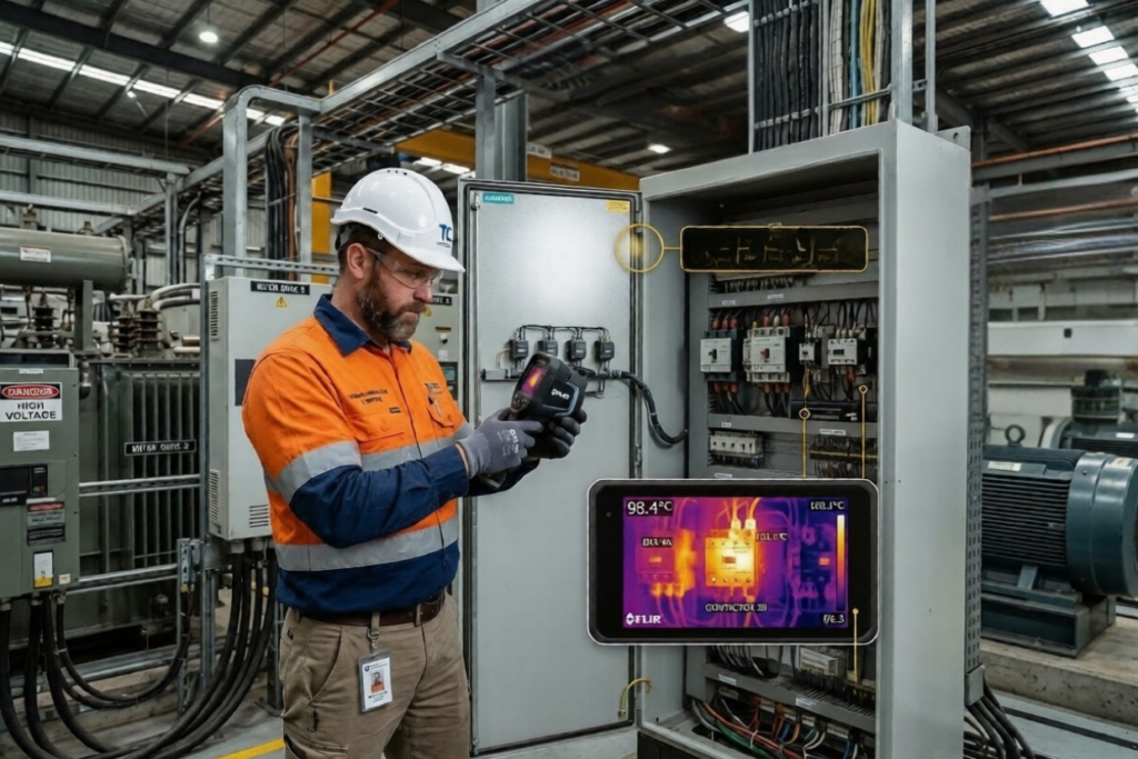
Thermal imaging is non-contact, meaning you can safely scan high-voltage electrical panels, moving equipment, or inaccessible areas without risk. Visual inspections require proximity and often mean stopping equipment. Thermal imaging scans large systems in minutes; visual inspection takes hours. Thermal data creates a permanent record of thermal patterns, enabling trend analysis over time. Visual inspection relies on inspection notes and photos, which don’t scale for long-term monitoring.
Thermal Imaging vs Multimeter Testing
A multimeter tests one point at a time. Thermal imaging scans hundreds of points simultaneously. Multimeter readings measure electrical properties; thermal imaging measures surface temperature. For detecting early faults across many components, thermal imaging is faster and more comprehensive.
When Thermal Imaging Should NOT Be Used Alone
A thermal hotspot might indicate a loose connection, high resistance, overload, or reflective heat from nearby sources. Confirmatory testing, multimeter readings, resistance checks, or visual inspection, clarifies root cause. Some failures are internal with no surface temperature change; bearing or electrical winding faults inside sealed equipment may not show thermal anomalies until very late stages.
Practical Implementation: What Professionals Should Consider
Resolution and Sensitivity (Why Specs Matter)
Thermal sensitivity (NETD) determines the smallest temperature difference the camera detects. Better sensitivity catches subtle faults earlier. Resolution (pixel count) determines how clearly you can pinpoint hotspots. A 320×240 camera is adequate for large equipment; a 640×480 camera resolves faults on small components more precisely.
Environmental Considerations
Ambient temperature, reflective surfaces, wind, and sunlight all influence thermal readings. A shiny transformer reflects sunlight, appearing artificially hot. Wet surfaces reflect infrared differently. Best practice: scan during stable conditions, indoor environments, overcast days, or when equipment is under load (to trigger faults that only appear during operation).
Operator Skill and Interpretation Accuracy
An untrained operator may see a 10°C temperature rise and declare a failure, or miss a 50°C hotspot because they don’t know what normal patterns look like. Trained thermographers understand emissivity, environmental factors, baseline comparison, and equipment-specific thermal signatures. They distinguish genuine faults from environmental artifacts. Poor interpretation leads to false alarms and wasted maintenance efforts.
Maintenance and Calibration Requirements
Regular calibration ensures measurements stay accurate. Most facilities recalibrate cameras annually. Maintenance involves lens cleaning, sensor checks, and software updates.
Common Mistakes When Using a Thermal Imaging Camera
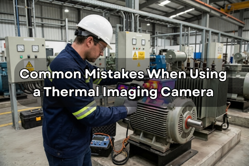
Ignoring emissivity settings. Using default emissivity (typically 0.95) on shiny aluminum or polished stainless steel produces false readings. Always adjust emissivity for material type.
Scanning without load conditions. An idle motor doesn’t show bearing wear; a powered motor does. Scan equipment under normal or peak operating conditions to trigger faults.
Overlooking background reflections. Cold surfaces behind warm equipment can reflect onto the target, creating false hotspots. Change viewing angle or mask reflective sources.
Misinterpreting normal heat patterns as faults. Some equipment naturally runs hotter. A transformer rated for 100°C operation shows 80°C under normal load, not a fault, normal operation. Establish equipment-specific baselines first.
How to Integrate Thermal Imaging Into a Predictive Maintenance Plan
Establishing Inspection Frequency
Risk-based scheduling means critical assets (transformers, critical motors, power distribution) get inspected more frequently, monthly or quarterly. Lower-risk equipment gets inspected annually. As you build thermal history, trends guide frequency adjustments.
Creating Baseline Thermal Profiles
The first thermal scan establishes normal operating temperature. Subsequent scans compare against this baseline. A motor baseline might show bearing temperature of 65°C under full load; a later scan showing 85°C signals bearing deterioration. Baselines eliminate guesswork.
Documentation and Trend Analysis
Store thermal images and temperature data systematically. Compare thermal images month-to-month and year-to-year. Identify progressive deterioration, a bearing temperature rising 2°C per month predicts failure within six months, triggering planned replacement before breakdown.
Working With Certified Inspection Providers
Professional thermographers hold credentials from the Infrared Training Center or similar bodies. They understand regulatory compliance, reporting standards, and equipment-specific diagnostics.
Risks, Limitations, and Real-World Constraints
Surface temperature vs internal condition: Thermal imaging shows surface heat, not internal wear. A sealed bearing with internal damage may not emit external heat until failure is imminent.
Environmental false readings: Reflections, humidity, emissivity errors, and ambient temperature swings create misleading hotspots. Context and baseline comparison mitigate this.
Cost vs ROI: Thermal cameras cost $5,000–$50,000+; annual inspections add labor costs. ROI appears to prevent downtime and extended equipment life, typically 12–24 months. Larger facilities realize ROI faster.
Regulatory and safety compliance: Some industries mandate thermography for equipment certification. Plan inspections to align with compliance schedules.
Conclusion: Using Thermal Imaging as a Preventive, Not Reactive, Tool
Hidden equipment faults escalate silently, turning into expensive failures. Thermal imaging detects the early heat signatures that precede breakdown, giving you weeks or months to plan repairs instead of managing crises.
Thermal imaging works best as part of a predictive maintenance strategy: establish baselines, inspect on risk-based schedules, document trends, and confirm findings with complementary diagnostics. It’s not a replacement for visual inspection, multimeter testing, or vibration analysis, it’s a powerful partner to these methods.
Success depends on proper implementation: trained operators, correct emissivity settings, stable environmental conditions, and systematic documentation. When used correctly, a thermal imaging camera becomes a risk-reduction instrument that protects equipment, extends asset life, and prevents the costly surprises that reactive maintenance allows.